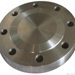
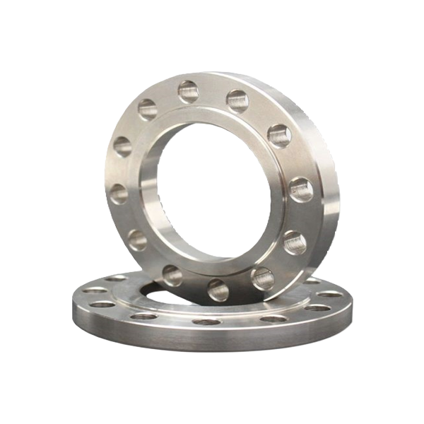
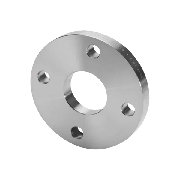
Flange ASME/ANSI B16.5-1996 And B16.47-1996
A flange is a method of connecting pipes, valves, pumps and other equipment to form a piping system. It also provides easy access for cleaning, inspection or modification. Flanges are usually welded or screwed. Flanged joints are made by bolting together two flanges with a gasket between them to provide a seal.
Specification:
| ASME/ANSI B16.5-1996 and B16.47-1996 | |||
| Tolerances on flange dimensions (ASME/ANSI B16.5 and B16.7, and MSS SP-44) | |||
| Dimension | Range | Tolerance | |
| in | mm | ||
| General and Blind Flanges(For blind flange dimendions see page 8-23 for B16.5, page8-46 for B16.47 Series A/ MSS SP-44 and page 8-51 for B16.47 Series B/ API 605): | |||
| G(raised face diameter) | ≤NPS 24 | ±0.03 | ±0.76 |
| ≥NPS 26,with 0.06 in raised face | ±0.08 | ±2.03 | |
| ≥NPS 26,with 0.25 in raised face | ±0.04 | ±1.02 | |
| I(bolt hole diameter) | All | No tolerance in B16.5 or B 16.47 | |
| J(bolt circle diameter) | All | ±0.06 | ±1.52 |
| Center to center of adjacent bolt holes | All | ±0.03 | ±0.76 |
| Eccenticity of bolt circle and machined facing diameters | ≤NPS 2½ | ±0.03 | ±0.76 |
| ≥NPS 3 | ±0.06 | ±1.52 | |
| Weld Neck Flanges1 (For dimensions see page 8-10 for B 16.5, page 8-46 for B16.47 Series A/ MSS SP-44 and page 8-51 for B16.47 Series B/ API 605): | |||
| D(overall length) | ≤NPS 4 | ﹢0.06 | ﹢1.52 |
| NPS 5 to 10 | ﹢0.06,﹣0.12 | ﹢1.52,﹣3.05 | |
| NPS 12 to 24 | ﹢0.12,﹣0.18 | ﹢3.05,﹣4.57 | |
| ≥NPS 26 | ±0.19 | ±4.83 | |
| Thickness of hub | All | >87.5% of pipe nominal wall thickness | |
| Slip on(see page 8-17),Lap Joint(see page8-32) and Socket Welding(see page 8-30 for dimensions) Flanges: | |||
| B(inside diameter,or bore) | ≤NPS10 | ﹢0.03,﹣0.0 | ﹢0.76,﹣0.0 |
| ≥NPS12 | ﹢0.06,﹣0.0 | ﹢1.52,﹣0.0 | |
| Threaded Flanges (see page 8-40 for dimensions): | |||
| B(counterbore) (Not applicable for Class 150 lb | ≤NPS10 | ﹢0.03,﹣0.0 | ﹢0.76,﹣0.0 |
| ≥NPS12 | ﹢0.06,﹣0.0 | ﹢1.52,﹣0.0 | |
Flanges Catalog
*For more information about buttwelded stub end, please contact us.


